Mingdi Air can let you learn the selection of air-conditioning pumps in ten minutes.
As an important part of the central air conditioning water system, the pump is suitable for selection. This has always been a question worth exploring. If the pump head selected by the design is too large, the rich head will lead to an increase in the exchange rate, and the increase in the flow rate will increase the pump noise. In addition, the motor load and current will increase, causing problems such as motor burning. If the choice is too small, it will lead to insufficient condensation at the end, which will affect the cooling effect. Today, Xiaobian conducts a detailed analysis of the pump selection calculation for air conditioners, allowing you to fully understand the selection of air-conditioning pumps in ten minutes.

The calculation of the selection of air-conditioning pumps can be directly estimated by the calculation formula. The detailed calculation of the points and the comprehensive considerations are accurate calculations. The selection calculation generally includes pump flow calculation, pump head simple estimation method, and air conditioning pump head practical estimation method. The specific selection algorithm is as follows:
1. Determination of pump flow
Flow rate is one of the important performance data of the pump selection, which is directly related to the production capacity and conveying capacity of the entire unit. The normal, minimum, and maximum flow rates of the pump are usually calculated in the design of the design institute. When the pump is selected, the normal flow rate is based on the maximum flow rate. When there is no maximum flow rate, 1.1 times the normal flow rate can be taken as the maximum flow rate.
Pump water flow: Generally, the flow rate of the pump is selected according to the product sample (for example, the flow rate of the optional air source unit is 1.1 to 1.2 times (1.1 for a single unit, 1.2 for two units) or according to the following formula:
Q=1.163L*ΔT
---Q is the air source host cooling capacity
---L is the system cooling water flow
---ΔT is the system temperature difference
L(m3/h)= Q(kW)/(4.5~5)°Cx1.163X(1.1~1.2)
2. Calculation of pipe diameter of water system
All water pipe diameters in an air conditioning system are generally calculated according to the following formula:
D(m)=√L(m3/h) /0.785x3600xV(m/s)
L----the water flow of the pipe section (the first step has been calculated)
V----the allowable water flow rate of the pipe segment
Determination of flow rate: Generally, when the pipe diameter is between DN40 and DN50, the recommended flow rate is about 1.0m/s; when the pipe diameter is smaller than DN40, the recommended flow rate should be less than 0.8m/s; when the pipe diameter is larger than DN50, the flow rate is Can be increased. The calculation should be done to pay attention to the correspondence between the pipe diameter and the recommended flow rate.
>>>>The current size specifications of the pipe diameter are: DN15, DN20, DN25, DN32, DN40, DN50, DN65, DN80 .......
>>>> Note: Generally, when selecting a water pump, the inlet and outlet pipe diameter of the pump should be smaller than the pipe diameter of the pipe section where the pump is located. For example, if the pipe diameter of the pipe section is DN25, the inlet and outlet pipe diameter of the selected pump should be DN20.
3. Determination of pump head
The composition of the air conditioning pump head:
Hmax=△P1+△P2
---△P1 is the resistance along the pipeline.
---△P2 is the local resistance of the pipeline.
(1) Resistance along the system
The pressure loss along the path refers to the continuous and consistent pressure loss in the pipeline. Generally, the most unfavorable loop in the pipeline is found. The farthest and most resistant branch pipe loop in the pipe network system is called the pipe network system. The most unfavorable loop.
△P1=the most unfavorable pipe length* frictional resistance
Generally, the estimated loss per 100 meters of pipe length is 5mH2O.
(2) Local resistance of the system
Partial pressure loss refers to the special component in the piping system, which changes the direction of water flow or narrows the local water flow channel (such as diameter reduction, tee, valve, joint, filter, etc.). The local resistance is mainly composed of the following
1. Water resistance of air source unit: generally 6~8mH2O; (see product sample for specific values)
2. End device (air treatment unit, fan coil, etc.) air cooler or evaporator water resistance: generally 5~7mH2O; (see product sample according to body value)
3. Backwater filter resistance, generally 3~5mH2O;
4. Valve (check valve) water resistance: generally one is 3mH2O;
5. Local resistance loss of water pipe tee and joint of refrigeration system: generally 3~4mH2O;
In summary, based on the calculated total resistance, taking a safety factor of 10%, the pump head is obtained.
>>>> Note: The calculation of the head should be based on the specific conditions of the refrigeration system. It is not allowed to copy the experience value at will!
4. Determination of pump model, number of units and standby rate
According to the two main performance parameters of the pump flow and head calculated above, the specific model is determined on the spectrum or series characteristic curve. The operation is as follows:
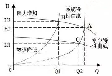
Using the pump characteristic curve, find the required flow value on the abscissa, find the required lift value on the ordinate, and draw the vertical or horizontal line from the two values up and to the right respectively. The intersection of the two lines falls on the characteristic curve. This pump is the pump to be selected

Under normal circumstances, customers can submit their "basic conditions for pump selection" to the corresponding pump manufacturer, the model of the pump given by it
In the domestic system, generally only one pump is used for normal operation, because one large pump is equivalent to two small pumps working in parallel, (the head and flow are the same), and the large pump is higher than the small pump, so energy saving From the perspective, you can choose a large pump instead of two small pumps, but in the following cases, consider two pumps in parallel:
1, the flow is very large, one pump can not reach this flow
2. For large pumps that require a 50% reserve rate, two smaller pumps can be changed to work.
The above is the selection step of the pump in the engineering design. In fact, the basic situation is similar in the home system, and the flow and head are well determined.
